
MxCAD Basic Drawing (Advanced): Polyline Creation
In the previous article "Basic Drawing in MxCAD," we learned how to draw primitive entities and were introduced to the built-in command system of MxCAD, which includes the polyline command Mx_Pline. Invoking it took just one line of code — ready to use out of the box. Yet if you open any real engineering drawing, you will find that the most frequently used entity is the polyline: building walls, municipal pipelines, road edges, and plot boundaries are almost all composed of it.
Why is the polyline so important? Because it is a compound entity where "one entity replaces many" — it can carry both straight segments and arc segments, and comes with its own width and geometric properties. As an advanced edition of basic drawing, this article takes you deep into the polyline and recreates the AutoCAD PLINE command interaction on the web.
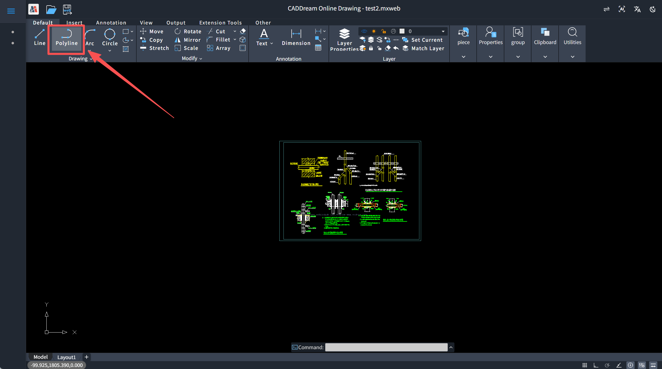
1. Introduction to Polylines
1. What Is a Polyline
A polyline is a single entity formed by connecting multiple vertices in sequence. Between adjacent vertices there can be either a straight segment or an arc segment. Its most essential difference from individual line segments is that, no matter how many segments it contains, it is always "one object" in the drawing database.
- Selection and editing work on the whole entity: a pipeline with 200 vertices can be selected as a whole with one click — moving or deleting it is a single operation;
- Built-in geometric properties: total length and enclosed area can be queried directly, forming the basis of quantity takeoff;
- Whole-entity transformations: operations such as offset (drawing double-line walls) and explode (reducing it back to primitives) naturally operate on it.
In mxcad, the polyline entity is represented by the McDbPolyline class. The simplest form of drawing a polyline is to add vertices in order and then submit:
import { McDbPolyline, MxCpp } from "mxcad";

const pl = new McDbPolyline();
pl.addVertexAt(pt1);                          // Add vertices in order
pl.addVertexAt(pt2);
pl.addVertexAt(pt3);
pl.addVertexAt(pt4);
pl.isClosed = true;                           // Close the polyline
MxCpp.getCurrentMxCAD().drawEntity(pl);       // Submit for drawing
2. The addVertexAt Method
In addition to writing vertex coordinates, the addVertexAt method provided by mxcad can also set two categories of per-vertex properties — bulge and width:
- Vertex: the basic building block of a polyline, defining the path direction;
- Bulge: determines whether the span between two adjacent vertices is a straight segment or an arc;
- Width: controls the thickness of the segment, with gradient support.
/**
 * Adds a vertex at the given position
 * @param pt vertex coordinates
 * @param bulge bulge value (default 0, i.e., a straight segment)
 * @param startWidth starting width (default 0)
 * @param endWidth ending width (default 0)
 * @param index insertion position (defaults to appending at the end)
 */
addVertexAt(pt, bulge?, startWidth?, endWidth?, index?): boolean
2. Three Core Concepts of the Polyline
1. Vertex
Vertices are connected into a path in the order they are added, and they are the most basic operational unit of a polyline. Common APIs around vertices are as follows:
const num = pl.numVerts();               // Total number of vertices
const pt = pl.getPointAt(2).val;         // Read the coordinates of vertex 2
pl.setPointAt(2, newPt);                 // Move vertex 2
pl.removeVertexAt(2);                    // Delete vertex 2
pl.isClosed = true;                      // Close: the last vertex automatically connects back to the first
One point deserves special attention: vertices are ordered, and the order of vertices determines the direction of the polyline. For example, the tangent calculation for arcs in a polyline depends on the sequence of the vertices.
2. Bulge
Just as Object Snap uses numeric codes to represent snap modes, a polyline uses a single number — the bulge — to fully describe an arc segment.
Definition of bulge: the bulge equals the tangent of one quarter of the arc's included angle (central angle), i.e., bulge = tan(θ/4), where θ is the central angle subtended by the arc segment (in radians). Three rules follow from the definition:
- The sign indicates direction:
bulge > 0is a counterclockwise arc,bulge < 0is a clockwise arc; - Characteristic values:
bulge = 0is a straight segment;|bulge| = 1is exactly a semicircle (tan45° = 1); - Where it is stored: the bulge is attached to the starting vertex of the arc segment, describing the span from the current vertex to the next one.
For daily development, this quick-reference table is all you need to remember:
| Included angle θ | bulge = tan(θ/4) | Note |
|---|---|---|
| 0° | 0 | Straight segment |
| 90° | √2 − 1 ≈ 0.4142 | Quarter circle, commonly used in fillets |
| 180° | 1 | Semicircle |
| 270° | √2 + 1 ≈ 2.4142 | Major arc |
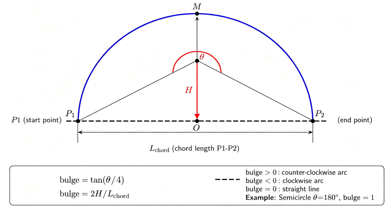
Manual conversion of bulge values is tedious and error-prone, so mxcad provides the ready-made utility function MxCADUtility.calcBulge(). Simply provide the start point of the arc, any point on the arc, and the endpoint, and you get the bulge of the target arc directly:
import { MxCADUtility } from "mxcad";

const ret = MxCADUtility.calcBulge(startPt, arcMidPt, endPt);
if (ret.ret) {
    console.log(ret.val);   // Bulge value; can be used directly as the 2nd argument of addVertexAt
}
For a polyline already drawn on the drawing, bulge can also be read or written by index:
const bulge = pl.getBulgeAt(2);   // Read the bulge of vertex 2
pl.setBulgeAt(2, 0);              // Set to 0: that segment becomes a straight line
3. Width
The width property of the polyline is often overlooked, but it is key to schematic-level drawing. Width has two levels:
Global width (constantWidth): a uniform thickness across the whole polyline — just set one property:
tspl.constantWidth = 10; // The whole polyline has width 10Per-vertex width (addVertexAt): the 3rd and 4th parameters of
addVertexAtare the starting width and ending width at that vertex, and the segment width transitions linearly from the starting value to the ending value. With this, an annotation line with an arrowhead can be drawn in a few lines:tsconst pl = new McDbPolyline(); pl.addVertexAt(pt1, 0, 4, 4); // Constant-width segment: the arrow shaft pl.addVertexAt(pt2, 0, 12, 0); // Gradient segment: width tapers from 12 to 0, forming the arrowhead pl.addVertexAt(pt3);
For a polyline already drawn on the drawing, use setWidthsAt / getWidthsAt to read or write width by index.
// Set the width of the segment at vertex 0: starting width 10, ending width 10 (constant-width segment)
pl.setWidthsAt(0, 10, 10);

// Read the width information of the segment at vertex 0
const width = pl.getWidthsAt(0);
if (width.ret) {
    // val1 is the starting width, val2 is the ending width
    console.log(width.val1, width.val2);
}
3. Building a Complete Polyline Drawing Command
The previous chapter introduced the three core concepts of the polyline. This chapter builds a polyline drawing command Mx_Pline from scratch, implementing on the web the same interaction as AutoCAD's PLINE: mixed line/arc drawing, variable width, undo, close, and real-time dynamic preview. This chapter is also a comprehensive application of the three concepts — vertex, bulge, and width.
The implementation of the command is divided into five steps: planning the interaction options, building the basic structure for data collection and entity generation, implementing line mode and arc mode separately, finalization, and finally integrating all parts into a complete command and registering it.
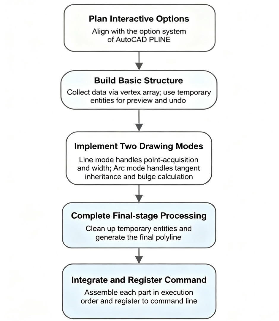
1. Interaction Design
Before writing code, first plan the interaction form of the command. MxCAD consistently aligns with AutoCAD's operational habits, so we adopt PLINE's option system directly. The implementation of PLINE mainly consists of two modes:
- Line mode: centered on vertices + width;
- Arc mode: centered on bulge.
Based on the polyline drawing operation in AutoCAD, the implementation steps can be divided as follows: first collect vertices and build entities, then handle width, and finally handle bulge.
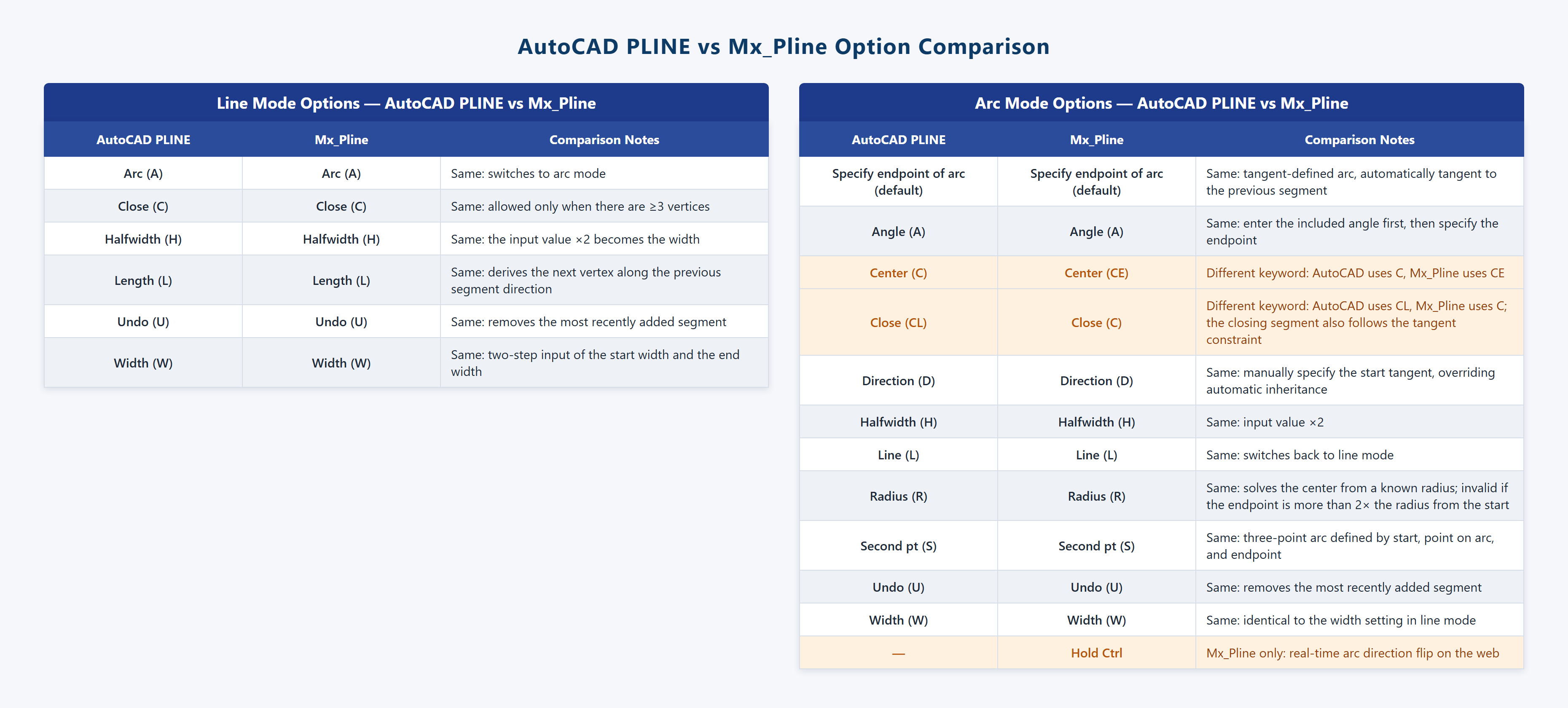
2. Basic Structure of the Command
2.1 Collecting Vertex Data
The command needs to record every vertex the user confirms in an array. Looking back at the parameters of addVertexAt — coordinates, bulge, starting width, ending width — each record in the array contains exactly these four fields. The benefit of this design is that, when generating the final entity, you simply call addVertexAt record by record:
// Vertex data: coordinates + bulge + starting/ending widths
interface VertexData {
    pt: McGePoint3d;
    dBulge: number;
    dStartWidth: number;
    dEndWidth: number;
}

const vecData: VertexData[] = [];
// Add the start point: the bulge of a straight segment is 0, widths default to 0
vecData.push({ pt: firstPoint, dBulge: 0, dStartWidth: 0, dEndWidth: 0 });
2.2 Temporary Entities: Real-Time Display and Undo
During the interaction, each confirmed segment must be displayed immediately, and undo must be able to roll it back. Temporary entities are introduced for this purpose: every time a segment is confirmed, a two-vertex polyline is drawn with the latest two vertices for temporary display, and its ID is recorded in vecTmpObjectId; on undo, the corresponding temporary entity is deleted; when the command ends, all temporary entities are deleted, and the final polyline is generated in one go from the complete vertex data:
// Commit a segment: draw a temporary polyline with the latest two vertices
function commitSegment() {
    const len = vecData.length;
    if (len < 2) return;
    const seg = new McDbPolyline();
    seg.addVertexAt(vecData[len - 2].pt, vecData[len - 2].dBulge,
        vecData[len - 2].dStartWidth, vecData[len - 2].dEndWidth);
    seg.addVertexAt(vecData[len - 1].pt);
    vecTmpObjectId.push(mxcad.drawEntity(seg));
}

// Undo (U): pop the vertex data + delete the latest temporary entity
function undoSegment() {
    if (vecData.length <= 1) return;
    vecData.pop();
    vecTmpObjectId[vecTmpObjectId.length - 1].erase();
    vecTmpObjectId.pop();
}
Data collection and entity generation are separated from each other: the vertex array stores the data, temporary entities provide real-time display, and the final entity is generated when the command ends.
2.3 Main Loop and Mode Switching
The body of the command is a loop. A boolean variable isDrawLine marks whether the command is currently in line mode or arc mode; the loop switches between the two interaction branches accordingly, with the keywords A (Arc) and L (Line) used to switch modes:
while (true) {
    if (isDrawLine) {
        // ---- Line mode (see Section 3) ----
    } else {
        // ---- Arc mode (see Section 4) ----
    }
}
With the basic structure defined, we now implement the logic of the two branches separately.
3. Line Mode: Vertex Collection and Width Setting
The main flow of line mode is: get a point, save the vertex data, commit the temporary segment; the keyword branches handle width, length, undo, and close:
const getNextPoint = new MxCADUiPrPoint();
getNextPoint.setMessage("\nSpecify next point:");
// Keywords change dynamically with the vertex count: Close is allowed only with ≥3 vertices (consistent with AutoCAD)
let sKeyWord = "[Arc(A)/Width(W)/Length(L)/Halfwidth(H)]";
if (vecData.length >= 3) sKeyWord = "[Undo(U)/Arc(A)/Width(W)/Length(L)/Halfwidth(H)/Close(C)]";
else if (vecData.length >= 2) sKeyWord = "[Undo(U)/Arc(A)/Width(W)/Length(L)/Halfwidth(H)]";
getNextPoint.setKeyWords(sKeyWord);

// Dynamic preview: draw the rubber-band segment "last vertex → cursor" in real time as the cursor moves
const drawData = vecData[vecData.length - 1];
getNextPoint.setUserDraw((currentPoint, pWorldDraw) => {
    const pl = new McDbPolyline();
    pl.addVertexAt(drawData.pt, drawData.dBulge, drawData.dStartWidth, drawData.dEndWidth);
    pl.addVertexAt(currentPoint);
    pWorldDraw.drawMcDbEntity(pl, true);   // Second argument true: preview only, not written to the database
});

const ptNext = await getNextPoint.go();
if (ptNext !== null) {
    // Point acquired: save the new vertex data (bulge 0), commit the temporary segment
    vecData.push({ pt: ptNext, dBulge: 0, dStartWidth, dEndWidth });
    commitSegment();
} else if (getNextPoint.getStatus() === MrxDbgUiPrBaseReturn.kKeyWord) {
    if (getNextPoint.isKeyWordPicked("A")) {
        isDrawLine = false;                    // Switch to arc mode
    } else if (getNextPoint.isKeyWordPicked("W")) {
        // Width: two-step input for starting width and ending width
        const getWidth = new MxCADUiPrDist();
        getWidth.setMessage("Specify starting width");
        if (await getWidth.go() === null) break;
        dStartWidth = getWidth.value();
        getWidth.setMessage("Specify ending width");
        if (await getWidth.go() === null) break;
        dEndWidth = getWidth.value();
        // Width is written back to the current vertex and applies to the next segment;
        // the ending width carries over as the default for subsequent segments
        vecData[vecData.length - 1].dStartWidth = dStartWidth;
        vecData[vecData.length - 1].dEndWidth = dEndWidth;
        dStartWidth = dEndWidth;
    } else if (getNextPoint.isKeyWordPicked("C")) {
        isClose = true; break;                 // Close
    } else if (getNextPoint.isKeyWordPicked("U")) {
        undoSegment();                         // Undo
    }
    // H Halfwidth (input value ×2) and L Length (compute the vertex along the direction of the previous segment) follow similar logic, omitted here
} else {
    break;   // Right-click/Enter to finish
}
Two key details here:
- Dynamic preview is implemented via the
setUserDrawcallback; passingtrueas the second argument means preview only without writing to the database, so preview graphics are never written into the drawing; - The width application rule: width is written back to the current vertex (applying to the segment about to be drawn), and the ending width carries over as the default starting width for subsequent segments — consistent with the persistent-width rule of AutoCAD PLINE.
4. Arc Mode: Tangent Continuity and Bulge Calculation
4.1 Tangent Continuity: Ensuring Smooth Arc Connections
After switching to arc mode, the first task is to calculate the tangent at the start point of the current arc segment. AutoCAD specifies that an arc segment is tangent to the previous segment by default — if the previous segment is a line, the tangent is the direction of the line; if the previous segment is an arc, the tangent is the tangent direction at the endpoint of that arc. The implementation follows:
let vecArcTangent = new McGeVector3d();
if (vecData.length < 2) {
    // The very first segment is an arc: no reference available, take the horizontal direction as the tangent
    vecArcTangent.copy(McGeVector3d.kXAxis);
} else {
    const size = vecData.length;
    const pt1 = vecData[size - 2].pt;        // Start point of the previous segment
    const dBulge = vecData[size - 2].dBulge; // Bulge of the previous segment
    const pt2 = vecData[size - 1].pt;        // Endpoint of the previous segment (start point of the current arc)

    if (dBulge === 0) {
        // The previous segment is a line: tangent = direction of the line
        vecArcTangent = pt2.sub(pt1);
    } else {
        // The previous segment is an arc: build a temporary polyline and get the first derivative (tangent vector) at its endpoint
        const tmpPl = new McDbPolyline();
        tmpPl.addVertexAt(pt1, dBulge);
        tmpPl.addVertexAt(pt2);
        const tmpVec = tmpPl.getFirstDeriv(new McGePoint3d(pt2.x, pt2.y, 0));
        if (tmpVec.ret) vecArcTangent = tmpVec.val;
        else vecArcTangent.copy(McGeVector3d.kXAxis);
    }
}
As mentioned above, the order of vertices determines the direction of the polyline. The sequence of vertices in vecData determines the direction of the "previous segment" here; based on this tangent, the new arc segment connects smoothly with the existing path.
4.2 Default Method: Specifying the Endpoint Directly (Arc Defined by Tangent)
Once the tangent is determined, the user only needs to specify the endpoint of the arc — the start point, the endpoint, and the tangent at the start point uniquely determine an arc segment. The helper function CalcArcBulge computes the bulge from these three values. The core idea is: the center lies on both the perpendicular bisector of the chord and the line perpendicular to the start tangent; intersecting the two lines gives the center; then pick the arc midpoint consistent with the tangent; finally, call calcBulge with the three points:
// ---------- Helper function: compute the bulge from start point, endpoint, and start tangent ----------
// Idea: the center lies on both the perpendicular bisector of the chord and the line perpendicular to the start tangent;
// intersect the two lines to get the center; pick the arc midpoint consistent with the tangent,
// then call calcBulge with the three points
function CalcArcBulge(firstPoint: McGePoint3d, nextPoint: McGePoint3d,
    vecArcTangent: McGeVector3d): number {
    if (firstPoint.isEqualTo(nextPoint)) return 0;

    // Midpoint of the chord, and the perpendicular bisector of the chord
    const midPt = firstPoint.c().addvec(nextPoint.c().sub(firstPoint).mult(0.5));
    const vecMid = nextPoint.c().sub(firstPoint);
    vecMid.rotateBy(Math.PI / 2, McGeVector3d.kZAxis);
    const tmpMidLine = new McDbLine(midPt, midPt.c().addvec(vecMid));

    // Line perpendicular to the start tangent
    const vecVertical = vecArcTangent.c();
    vecVertical.rotateBy(Math.PI / 2, McGeVector3d.kZAxis);
    const tmpVerticalLine = new McDbLine(firstPoint, firstPoint.c().addvec(vecVertical));

    // Intersect the two lines to get the center
    const aryPoint = tmpMidLine.IntersectWith(tmpVerticalLine, McDb.Intersect.kExtendBoth);
    if (aryPoint.isEmpty()) return 0;
    const arcCenPoint = aryPoint.at(0);
    const dR = arcCenPoint.distanceTo(firstPoint);

    // There are two candidate arc midpoints from the center; pick the one with the smaller angle to the tangent
    vecMid.normalize();
    vecMid.mult(dR);
    const arcMidPt1 = arcCenPoint.c().addvec(vecMid);
    const arcMidPt2 = arcCenPoint.c().subvec(vecMid);
    const vecArcDir1 = arcMidPt1.c().sub(firstPoint);
    const vecArcDir2 = arcMidPt2.c().sub(firstPoint);
    const arcMidPt = (vecArcDir1.angleTo1(vecArcTangent) > vecArcDir2.angleTo1(vecArcTangent))
        ? arcMidPt2 : arcMidPt1;

    return MxCADUtility.calcBulge(firstPoint, arcMidPt, nextPoint).val;
}getNextPoint.setUserDraw((currentPoint, pWorldDraw) => {
// While Ctrl is held, negate the tangent → the arc direction flips in real time
const tangent = isCtrl ? vecArcTangent.clone().negate() : vecArcTangent;
const dBulge = CalcArcBulge(startPt, currentPoint, tangent);
const pl = new McDbPolyline();
pl.addVertexAt(startPt, dBulge, dStartWidth, dEndWidth);
pl.addVertexAt(currentPoint);
pWorldDraw.drawMcDbEntity(pl, true);
});
const ptNext = await getNextPoint.go();
if (ptNext !== null) {
// Confirmed: write the bulge back to the current vertex, and push the new endpoint into the array.
// The bulge is written to the starting vertex of the arc segment; the bulge of the new endpoint stays at 0
vecData[vecData.length - 1].dBulge = CalcArcBulge(
startPt, ptNext, isCtrl ? vecArcTangent.clone().negate() : vecArcTangent);
vecData.push({ pt: ptNext, dBulge: 0, dStartWidth, dEndWidth });
commitSegment();
}4.3 Angle (A): Solving a Right Triangle from the Included Angle
If the user first enters the included angle of the arc and then specifies the endpoint, the problem can be solved with a right triangle: take the half-chord length as the opposite side, combine it with the angle to solve for the radius and the center-to-chord distance, then locate the arc midpoint, and finally hand it over to calcBulge:
const getBulge = (pt: McGePoint3d) => {
    // Midpoint of the chord and half-chord length (opposite side of the right triangle)
    const midPt = new McGePoint3d((pt.x + startPoint.x) / 2, (pt.y + startPoint.y) / 2);
    const oppositeSide = midPt.distanceTo(startPoint);
    // Solve the right triangle: radius = hypotenuse, center-to-chord distance = adjacent side
    const angleA = Math.PI / 2 - angle / 2;
    const radius = oppositeSide / Math.sin(angleA);
    const adjacentEdge = oppositeSide / Math.tan(angleA);
    // Offset the chord midpoint along the perpendicular by the "sagitta" (radius − center-to-chord distance)
    // to get the arc midpoint; Ctrl switches to the major arc direction
    const vet = midPt.sub(startPoint).rotateBy(Math.PI / 2).normalize()
        .mult(isCtrl ? -radius - adjacentEdge : radius - adjacentEdge);
    const midPoint = midPt.addvec(vet);
    return MxCADUtility.calcBulge(startPoint, midPoint, pt).val;
};
4.4 Other Arc Definition Methods
Following the same approach, the remaining arc definition methods can also be implemented:
- Second point (S): the start point, a point on the arc, and the endpoint define the arc directly; during preview,
McDbArc.computeArcfits the arc in real time, and after confirmation the bulge is computed; - Center (CE): the center plus the endpoint (or angle, or chord length) defines the arc; the angle between vectors distinguishes major from minor arcs; a chord length exceeding the diameter is reported as invalid;
- Radius (R): with a known radius, the center position is solved in reverse; an endpoint farther than 2×radius from the start point is likewise judged invalid;
- Direction (D): the user manually specifies the tangent at the start point, overriding the automatically inherited tangent — used when the exit direction of the arc must be forced.
The goal of all these methods is the same: calculate the bulge and write it into the current vertex.
4.5 The Ctrl Key: Direction-Switch Interaction on the Web
In desktop CAD, switching the direction of an arc requires going through command-line sub-options, whereas commands on the web can directly leverage browser keyboard events — holding Ctrl flips the arc direction in real time: in tangent-defined mode the tangent is negated, in angle mode the major arc is picked instead, and in three-point mode the point on the arc is mirrored about the center. Holding/releasing Ctrl while moving the cursor flips the preview in real time:
let isCtrl = false;
window.addEventListener("keydown", (e) => { if (e.key === "Control") isCtrl = true; });
window.addEventListener("keyup", () => isCtrl = false);
5. Finalization: Closing, Cleanup, and Final Submission
When the command ends, three tasks must be completed:
// 1. Closing in arc mode: the closing segment also follows the tangent constraint; compute its bulge with the current tangent
if (getNextPoint.isKeyWordPicked("C")) {
    vecData[vecData.length - 1].dBulge = CalcArcBulge(
        currentPt, firstPoint, isCtrl ? vecArcTangent.clone().negate() : vecArcTangent);
    isClose = true;
    break;
}

// 2. Erase all temporary entities
for (let i = 0; i < vecTmpObjectId.length; i++) {
    vecTmpObjectId[i].erase();
}

// 3. Generate the final polyline in one go from the complete vertex data
if (vecData.length > 1) {
    const pNew = new McDbPolyline();
    for (let i = 0; i < vecData.length; i++) {
        pNew.addVertexAt(vecData[i].pt, vecData[i].dBulge,
            vecData[i].dStartWidth, vecData[i].dEndWidth);
    }
    pNew.isClosed = isClose;
    return mxcad.drawEntity(pNew);
}
Finally, register the command with MxCAD so that it can be invoked from the command line just like built-in commands.
6. Integration: The Complete Mx_Pline Command
The previous five subsections implemented the individual parts of the command. The last step is to assemble them in execution order to form the complete drawPolyLine function. The correspondence between parts is as follows:
| Code location | Section | Content |
|---|---|---|
| Imports and helper function | 4.2 | CalcArcBulge: computes the bulge from start point, endpoint, and tangent |
| State variables | 2.1 / 4.5 | Vertex array vecData, temporary entity array, width variables, mode switch, Ctrl listener |
| Main loop – line branch | 3 | Point acquisition, width setting, undo, close, switch to arc mode |
| Main loop – arc branch | 4 | Tangent continuity, arc defined by tangent, bulge written back to the starting vertex |
| After the loop | 5 | Delete temporary entities, generate the final polyline |
The complete code is as follows:
import {
    McDb, McDbLine, McDbPolyline, McGePoint3d, McGeVector3d, McObjectId,
    MxCADUiPrPoint, MxCADUiPrDist, MxCADUtility, MxCpp, MxFun
} from "mxcad";

export async function drawPolyLine() {
    const mxcad = MxCpp.getCurrentMxCAD();

    // [2.1] Vertex array; [2.2] Temporary entity array
    const vecData: VertexData[] = [];
    const vecTmpObjectId: McObjectId[] = [];

    // Width variables: width of the current segment, also carried over as the default for subsequent segments
    let dStartWidth = 0;
    let dEndWidth = 0;

    // [2.3] Mode switch and close flag
    let isDrawLine = true;
    let isClose = false;

    // [4.5] Ctrl key listener: flip the arc direction in real time while held
    let isCtrl = false;
    const onKeydown = (e: KeyboardEvent) => { if (e.key === "Control") isCtrl = true; };
    const onKeyup = () => isCtrl = false;
    window.addEventListener("keydown", onKeydown);
    window.addEventListener("keyup", onKeyup);

    // [2.2] Commit a segment: draw a temporary polyline with the latest two vertices
    function commitSegment() {
        const len = vecData.length;
        if (len < 2) return;
        const seg = new McDbPolyline();
        seg.addVertexAt(vecData[len - 2].pt, vecData[len - 2].dBulge,
            vecData[len - 2].dStartWidth, vecData[len - 2].dEndWidth);
        seg.addVertexAt(vecData[len - 1].pt);
        vecTmpObjectId.push(mxcad.drawEntity(seg));
    }

    // [2.2] Undo (U): pop the vertex data + delete the latest temporary entity
    function undoSegment(getNextPoint: MxCADUiPrPoint) {
        if (vecData.length <= 1) return;
        vecData.pop();
        vecTmpObjectId[vecTmpObjectId.length - 1].erase();
        vecTmpObjectId.pop();
        getNextPoint.setLastInputPoint(vecData[vecData.length - 1].pt);
    }

    // Get the start point and add it to the vertex array
    const getFirstPoint = new MxCADUiPrPoint();
    getFirstPoint.setMessage("\nSpecify start point:");
    const firstPoint = await getFirstPoint.go();
    if (!firstPoint) return;
    vecData.push({ pt: firstPoint, dBulge: 0, dStartWidth: 0, dEndWidth: 0 });

    // [2.3] Main loop: switch interaction branches by mode
    while (true) {
        const getNextPoint = new MxCADUiPrPoint();

        if (isDrawLine) {
            // [3] Line mode
            getNextPoint.setMessage("\nSpecify next point:");
            // Keywords change dynamically with the vertex count: Close is allowed only with ≥3 vertices (consistent with AutoCAD)
            let sKeyWord = "[Arc(A)/Width(W)/Length(L)/Halfwidth(H)]";
            if (vecData.length >= 3) sKeyWord = "[Undo(U)/Arc(A)/Width(W)/Length(L)/Halfwidth(H)/Close(C)]";
            else if (vecData.length >= 2) sKeyWord = "[Undo(U)/Arc(A)/Width(W)/Length(L)/Halfwidth(H)]";
            getNextPoint.setKeyWords(sKeyWord);

            // Dynamic preview: draw the rubber-band segment "last vertex → cursor" in real time as the cursor moves
            const drawData = vecData[vecData.length - 1];
            getNextPoint.setUserDraw((currentPoint, pWorldDraw) => {
                const pl = new McDbPolyline();
                pl.addVertexAt(drawData.pt, drawData.dBulge, drawData.dStartWidth, drawData.dEndWidth);
                pl.addVertexAt(currentPoint);
                pWorldDraw.drawMcDbEntity(pl, true);
            });

            const ptNext = await getNextPoint.go();
            if (ptNext !== null) {
                // Point acquired: save the new vertex data (bulge 0), commit the temporary segment
                vecData.push({ pt: ptNext, dBulge: 0, dStartWidth, dEndWidth });
                commitSegment();
            } else if (getNextPoint.isKeyWordPicked("A")) {
                isDrawLine = false;                    // Switch to arc mode
            } else if (getNextPoint.isKeyWordPicked("W")) {
                // Width: two-step input for starting width and ending width
                const getWidth = new MxCADUiPrDist();
                getWidth.setMessage("Specify starting width");
                if (await getWidth.go() === null) break;
                dStartWidth = getWidth.value();
                getWidth.setMessage("Specify ending width");
                if (await getWidth.go() === null) break;
                dEndWidth = getWidth.value();
                // Width is written back to the current vertex and applies to the next segment;
                // the ending width carries over as the default for subsequent segments
                vecData[vecData.length - 1].dStartWidth = dStartWidth;
                vecData[vecData.length - 1].dEndWidth = dEndWidth;
                dStartWidth = dEndWidth;
            } else if (getNextPoint.isKeyWordPicked("H")) {
                // Halfwidth: same flow as Width, input value ×2 (implementation omitted)
            } else if (getNextPoint.isKeyWordPicked("L")) {
                // Length: compute the new vertex along the direction of the previous segment (implementation omitted)
            } else if (getNextPoint.isKeyWordPicked("C")) {
                isClose = true; break;                 // Close
            } else if (getNextPoint.isKeyWordPicked("U")) {
                undoSegment(getNextPoint);             // Undo
            } else {
                break;   // Right-click/Enter to finish
            }
        } else {
            // [4] Arc mode

            // [4.1] Tangent continuity: if the previous segment is a line, take the line direction;
            // if it is an arc, take the tangent at its endpoint
            let vecArcTangent = new McGeVector3d();
            if (vecData.length < 2) {
                vecArcTangent.copy(McGeVector3d.kXAxis);
            } else {
                const size = vecData.length;
                const pt1 = vecData[size - 2].pt;
                const dBulge = vecData[size - 2].dBulge;
                const pt2 = vecData[size - 1].pt;
                if (dBulge === 0) {
                    vecArcTangent = pt2.sub(pt1);
                } else {
                    const tmpPl = new McDbPolyline();
                    tmpPl.addVertexAt(pt1, dBulge);
                    tmpPl.addVertexAt(pt2);
                    const tmpVec = tmpPl.getFirstDeriv(new McGePoint3d(pt2.x, pt2.y, 0));
                    if (tmpVec.ret) vecArcTangent = tmpVec.val;
                    else vecArcTangent.copy(McGeVector3d.kXAxis);
                }
            }

            // This section implements only the default method (arc defined by tangent);
            // for Angle(A), Second point(S), Center(CE), Radius(R), Direction(D), see Sections 4.3–4.4
            getNextPoint.setMessage("\nSpecify endpoint of arc (hold Ctrl to switch direction)");
            getNextPoint.setKeyWords("[Line(L)/Width(W)/Halfwidth(H)]");

            const startPt = vecData[vecData.length - 1].pt;
            // [4.2] Dynamic preview: the cursor position is the endpoint; compute the bulge in real time and preview
            getNextPoint.setUserDraw((currentPoint, pWorldDraw) => {
                const tangent = isCtrl ? vecArcTangent.clone().negate() : vecArcTangent;
                const dBulge = CalcArcBulge(startPt, currentPoint, tangent);
                const pl = new McDbPolyline();
                pl.addVertexAt(startPt, dBulge, dStartWidth, dEndWidth);
                pl.addVertexAt(currentPoint);
                pWorldDraw.drawMcDbEntity(pl, true);
            });

            const ptNext = await getNextPoint.go();
            if (ptNext !== null) {
                // [4.2] Write the bulge back to the starting vertex of the arc segment; the bulge of the new endpoint stays at 0
                vecData[vecData.length - 1].dBulge = CalcArcBulge(
                    startPt, ptNext, isCtrl ? vecArcTangent.clone().negate() : vecArcTangent);
                vecData.push({ pt: ptNext, dBulge: 0, dStartWidth, dEndWidth });
                commitSegment();
            } else if (getNextPoint.isKeyWordPicked("L")) {
                isDrawLine = true;                     // Switch back to line mode
            } else if (getNextPoint.isKeyWordPicked("W")) {
                // Width setting, same as line mode (implementation omitted)
            } else if (getNextPoint.isKeyWordPicked("H")) {
                // Halfwidth setting, same as line mode (implementation omitted)
            } else if (getNextPoint.isKeyWordPicked("C")) {
                // [5] Closing in arc mode: compute the bulge of the closing segment with the current tangent
                vecData[vecData.length - 1].dBulge = CalcArcBulge(
                    startPt, firstPoint, isCtrl ? vecArcTangent.clone().negate() : vecArcTangent);
                isClose = true;
                break;
            } else if (getNextPoint.isKeyWordPicked("U")) {
                undoSegment(getNextPoint);             // Undo
            } else {
                break;   // Right-click/Enter to finish
            }
        }
    }

    // [5] Finalization
    // 1. Delete all temporary entities
    for (let i = 0; i < vecTmpObjectId.length; i++) {
        vecTmpObjectId[i].erase();
    }
    // 2. Generate the final polyline in one go from the complete vertex data
    if (vecData.length > 1) {
        const pNew = new McDbPolyline();
        for (let i = 0; i < vecData.length; i++) {
            pNew.addVertexAt(vecData[i].pt, vecData[i].dBulge,
                vecData[i].dStartWidth, vecData[i].dEndWidth);
        }
        pNew.isClosed = isClose;
        mxcad.drawEntity(pNew);
    }
    // 3. Remove the keyboard listeners
    window.removeEventListener("keydown", onKeydown);
    window.removeEventListener("keyup", onKeyup);
}

// Register the command
MxFun.on("init", () => {
    MxFun.addCommand("Mx_Pline", drawPolyLine);
});
A few notes:
- Completeness boundary: the code above is a complete, runnable framework covering point acquisition, width, undo, close, tangent-defined arcs, and dynamic preview; the Halfwidth and Length options are marked "implementation omitted", and the remaining arc definition methods (Angle, Second point, Center, Radius, Direction) can be added one by one following the approach of Sections 4.3 and 4.4;
- Assembly order: helper function → state variables → two local functions (
commitSegment/undoSegment) → start point acquisition → main loop → finalization, i.e., the natural "define first, use later" order; - Benefits of local functions:
commitSegmentandundoSegmentare defined as inner functions ofdrawPolyLine, so they can accessvecDataandvecTmpObjectIddirectly without extra parameters.
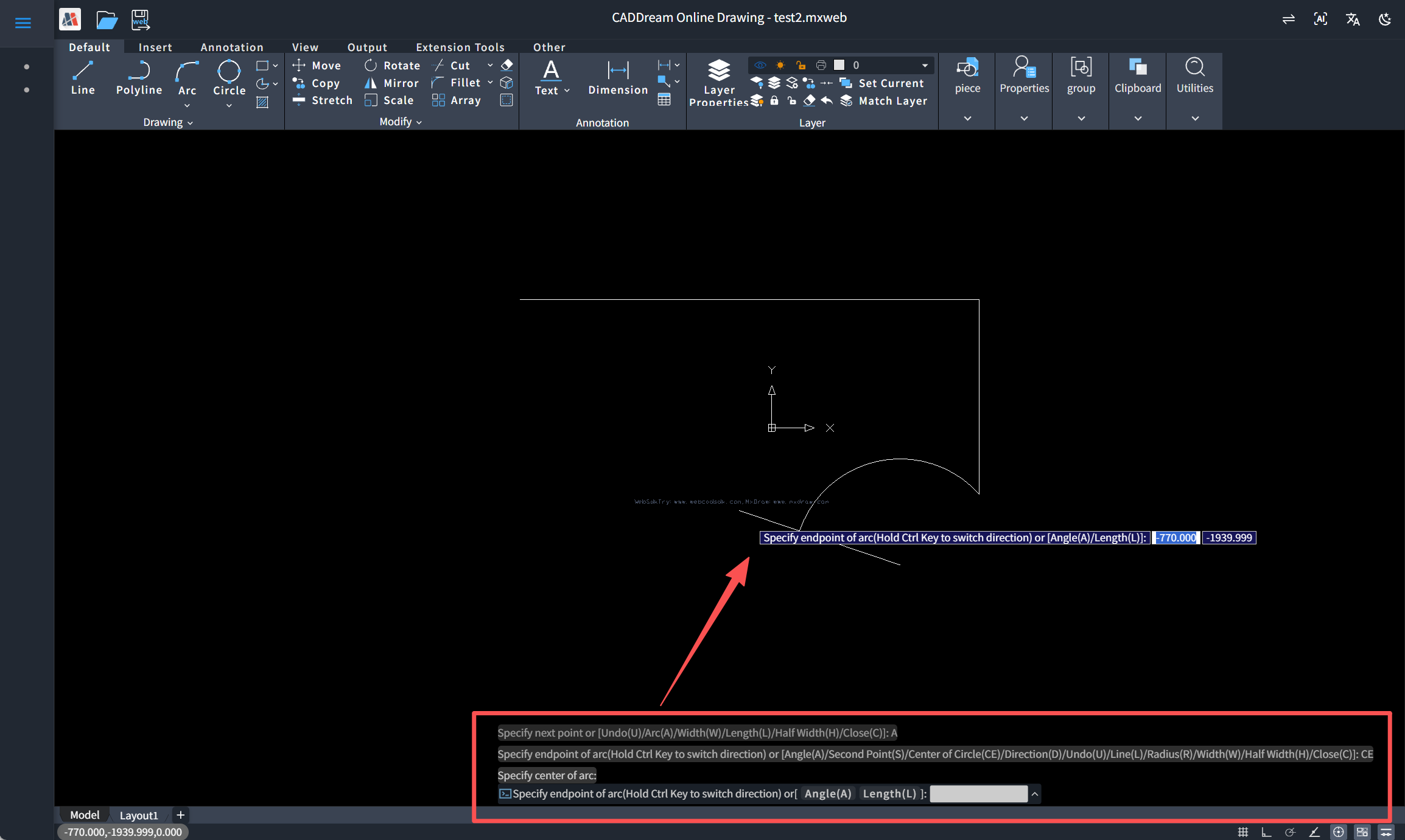
With this, a polyline command consistent with AutoCAD's PLINE interaction — supporting mixed line/arc drawing, variable width, undo, close, and real-time dynamic preview — is complete.
4. Summary
Looking back over the whole article, this chapter built a complete polyline drawing command from scratch. The implementation of the command follows a reusable approach: planning the interaction options → separating data collection from entity generation → implementing each mode separately → finalization → integration and registration. The main loop manages the interaction flow; the vertex array and temporary entities support real-time drawing and undo; the bulge reduces arc geometry to a single number. Once you master this method, implementing drawing commands for other compound entities also has a pattern to follow.
We hope this tutorial helps you understand the concepts of the polyline and the implementation of drawing commands. In the future, we will continue to publish the MxCAD feature series — stay tuned!